Resistor Calculator
Decode and encode 4-, 5-, and 6-band resistor colors, read SMD markings, combine resistor networks, and size an LED current-limiting resistor.
- resistor color code
- 4 band resistor
- 5 band resistor
- 6 band resistor
- resistor band decoder
Status: initial
Results
Awaiting calculation
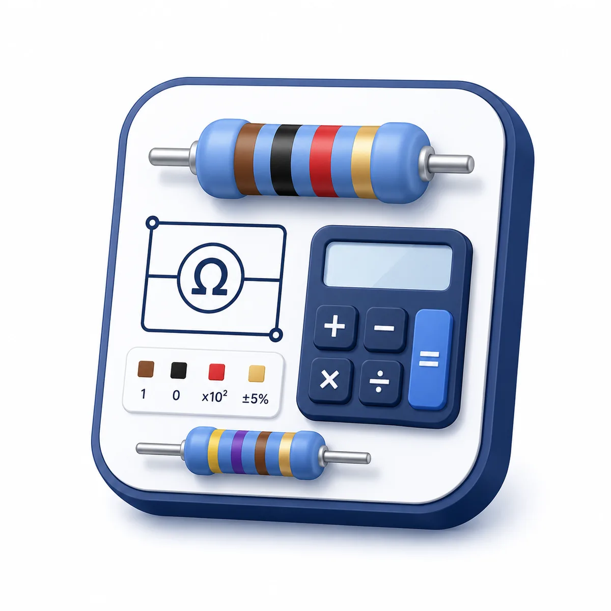
Brown · Black · Red · Gold
Decode the marking first, then examine the electrical context
The Resistor Calculator defaults to the dominant search task: decoding accessible, text-labelled 4-, 5-, and 6-band resistor colors into nominal resistance, tolerance range, and TCR. Separate workflows perform reverse color lookup, decode common SMD markings, compare series and parallel networks, and estimate an LED current-limiting resistor without pretending those tasks share the same assumptions.
Use it for identification, parts planning, and circuit checks
Use the page to read an axial resistor, find a practical band code, interpret common printed SMD codes, combine ideal resistors, or make a preliminary LED-resistor estimate. A marking is not a measurement or safety approval. Confirm the actual part, series, tolerance, TCR, voltage, pulse, noise, thermal, and environmental data before use.
Significant digits and a decade multiplier form the nominal resistance
Four-band codes contain two significant digits; five- and six-band codes contain three. The next band is a power-of-ten multiplier, followed by tolerance. A sixth band adds temperature coefficient in ppm/K. SMD numeric codes use related significant-digit and multiplier logic, while EIA-96 uses a two-digit preferred-value index plus a letter multiplier.
Variable explanations
Understand what each input and result means before calculating.
🎛️ Workflow
Choose color decode, reverse lookup, SMD marking, resistor network, or LED sizing. Each workflow shows only its relevant controls.
🎨 Band count
Four bands encode two digits, multiplier, and tolerance. Five bands add a third digit. Six bands add a TCR band after tolerance.
🔢 Significant colors
Black through white represent digits 0 through 9. The first significant band cannot be black; color names remain visible for accessibility.
✖️ Multiplier
Black through white represent powers from 10⁰ through 10⁹; gold and silver represent 10⁻¹ and 10⁻².
± Tolerance
Tolerance states the production range around nominal resistance. It is not the same as measurement uncertainty or total drift.
🌡️ TCR
The sixth band indicates nominal temperature coefficient in parts per million per kelvin. Actual curves and limits are component-specific.
🔎 Reverse lookup
Enter a resistance and choose a band count. The result reports the closest encodable significant digits and any rounding difference.
🧩 SMD marking
Supports common 3-digit, 4-digit, R-decimal, zero-ohm, and EIA-96 codes. Some packages are unmarked or use manufacturer-specific systems.
🔗 Network values
Enter values such as 220, 4.7k, or 1M. Series and parallel equivalents assume ideal resistors without wiring or parasitic effects.
💡 LED assumptions
Enter supply, nominal forward voltage, series LED count, and target current. Forward voltage varies with device, current, temperature, and production spread.
📚 Preferred series
E12, E24, and E96 provide standard values per decade. The result shows lower, nearest, and higher values instead of silently choosing one.
🔥 Power target
The LED workflow uses your own maximum utilization percentage to calculate rating context. Always apply the chosen component's real derating curves and other limits.
Reviewed by the Calculator.org.in Editorial Team
Formula behavior, validation cases, explanatory examples, and cited sources are checked before publication. This review supports educational accuracy and is not a substitute for qualified professional advice.
Last reviewed: 2026-08-10
Formula guide
See the calculation logic, variable definitions, and practical meaning.
4-band resistance
R = (10B₁ + B₂) × 10ᴹ
- B₁ and B₂ are color digits
- M is the multiplier exponent
The fourth band supplies tolerance.
5/6-band resistance
R = (100B₁ + 10B₂ + B₃) × 10ᴹ
- Three significant figures are encoded
- A sixth band adds TCR
Used for tighter preferred-value spacing and precision parts.
Tolerance limits
Rmin,max = Rnom × (1 ∓ tolerance/100)
- The range is around nominal resistance
It does not include temperature shift, aging, voltage coefficient, or measurement uncertainty.
Nominal TCR estimate
R(T) = Rref × [1 + αppm(T − Tref)/10⁶]
- α is the encoded ppm/K value
A first-order estimate; use the actual data sheet over the required temperature range.
3-digit SMD code
R = first two digits × 10ˡᵃˢᵗ ᵈⁱᵍⁱᵗ
- 103 means 10 × 10³ Ω
R may replace the decimal point for low values, such as 4R7.
4-digit SMD code
R = first three digits × 10ˡᵃˢᵗ ᵈⁱᵍⁱᵗ
- 1002 means 100 × 10² Ω
Typically provides three significant figures.
Series network
Rₛ = R₁ + R₂ + … + Rₙ
- The same current flows through each ideal series resistor
Equivalent resistance is the arithmetic sum.
Parallel network
1/Rₚ = 1/R₁ + 1/R₂ + … + 1/Rₙ
- The same voltage appears across ideal parallel branches
A zero-ohm branch makes the ideal parallel equivalent zero.
LED current-limiting resistance
R = (Vₛ − nVf) ÷ I
- Vf is a nominal LED forward voltage
- n is the number of series LEDs
Supply voltage must exceed the total forward voltage.
Resistor dissipation
P = I²R = (Vₛ − nVf)I
- Real rating selection requires manufacturer derating and worst-case conditions
The page compares power with a user-entered utilization target, not a universal safety rule.
Resistor examples
Follow realistic inputs through the calculation step by step.
Worked example
Brown-black-red-gold
- 1Choose four bands.
- 2Select brown, black, red, and gold.
- 3The result is 1 kΩ ±5%, or 950 Ω to 1.05 kΩ.
Worked example
Precision 10 kΩ
- 1Choose five bands.
- 2Brown-black-black-red-brown encodes 100 × 100.
- 3The result is 10 kΩ ±1%.
Worked example
Six-band TCR
- 1Choose six bands and set the sixth color.
- 2Enter reference and operating temperatures.
- 3Review the nominal TCR shift separately from the tolerance range.
Worked example
Reverse lookup for 4.7 kΩ
- 1Choose Find color bands.
- 2Enter 4.7 kΩ and four bands.
- 3The result is yellow-violet-red plus the selected tolerance color.
Worked example
Decode SMD 103
- 1Choose SMD marking.
- 2Enter 103.
- 3The first two digits are 10 and the final 3 means ×10³, giving 10 kΩ.
Worked example
Decode EIA-96 01C
- 1Choose SMD marking.
- 2Enter 01C.
- 3Index 01 maps to 100 and C means ×100, giving 10 kΩ.
Worked example
Combine 100 Ω, 220 Ω, and 1 kΩ
- 1Choose network and enter 100, 220, 1k.
- 2Series resistance is 1.32 kΩ.
- 3Parallel resistance is approximately 64.328 Ω.
Worked example
5 V supply and one 2 V LED
- 1Choose LED workflow and enter 20 mA.
- 2The ideal resistor is (5−2)/0.02 = 150 Ω.
- 3Review nearby preferred values and power-rating context before choosing a part.
Resistor mistakes
Avoid these common input and interpretation errors.
Reading from the wrong end
The tolerance band is commonly separated by a wider gap and placed on the right. Ambiguous, damaged, or nonstandard markings should be verified with documentation and a safe measurement.
Relying on color alone
Always pair visual color with the text label. Lighting, aging, coatings, and color-vision differences can make bands ambiguous.
Using black as the first significant band
Leading zero is not a valid first significant color in the supported axial code.
Confusing multiplier and tolerance
Gold and silver can be multipliers or tolerance colors depending on band position.
Treating tolerance as operating drift
Tolerance is initial production spread; temperature, voltage coefficient, aging, humidity, and load can add changes.
Assuming every 3-character SMD marking is EIA-96
Numeric 3-digit codes and EIA-96 alphanumeric codes use different rules. Manufacturer-specific markings also exist.
Assuming every SMD resistor is marked
Small packages and zero-ohm links may be unmarked or use alternate identifiers. Use the reel label, schematic, BOM, or measurement.
Measuring resistance in an energized circuit
Power must normally be removed and stored energy safely discharged. Other connected components can also distort in-circuit readings.
Adding parallel resistances directly
Parallel conductances add; the equivalent resistance is lower than the smallest positive branch resistance.
Ignoring resistor power sharing
Equivalent resistance alone does not show each component's current, voltage, dissipation, or thermal interaction.
Treating LED forward voltage as fixed
Vf varies with current, temperature, device bin, and production. A resistor estimate needs worst-case review.
Using one resistor for unmatched parallel LEDs
Parallel LED strings can share current unevenly. Each string may require individual current control or an appropriate driver.
Treating a wattage as the only limit
Working voltage, pulse energy, overload, temperature, mounting, enclosure, clearance, and failure mode may govern first.
Frequently asked questions
Quick answers to the questions users ask most often.
How do I read a 4-band resistor?
How is a 5-band resistor different?
What does the sixth band mean?
Which end should I read first?
What value is brown-black-red-gold?
What value is red-red-brown-gold?
What do gold and silver mean?
Can the calculator find colors from a resistance?
How does a 3-digit SMD code work?
How does a 4-digit SMD code work?
What does R mean in an SMD code?
What is an EIA-96 code?
How do I calculate resistors in series?
How do I calculate resistors in parallel?
What are E12, E24, and E96?
How is an LED resistor calculated?
Does the calculator select a safe resistor wattage?
References
Sources used to support the calculator guidance.
- IEC 60062: Marking codes for resistors and capacitors
- IEC 60063: Preferred number series for resistors and capacitors
- Vishay: Resistor Color Code Calculator Card
- Vishay: Resistor Color Code Card
- DigiKey: Resistor Color Code Calculator
- Texas Instruments: Analog Engineer's Pocket Reference
- Vishay: Pulse Load on Resistors
- NIST: SI Units—Electric current
- OpenStax University Physics Volume 2: Ohm's Law
- OSHA: Electrical safety
Related calculators
Continue with calculators that solve nearby problems.
Version history
A transparent record of calculator content updates.
- 1.0.0 · 2026-08-10
Initial standalone release with accessible 4/5/6-band decoding and visualization, reverse lookup, SMD and EIA-96 decoding, network equivalents, LED resistor sizing, preferred E-series values, tolerance ranges, and TCR context.